Once the system completely filled with water, all the circulator has to do is move it around. It helps to think of a heating system as a Ferris wheel. When a Ferris wheel turns, the weight going up balances the weight coming down. There’s no lifting going on here, there’s only turning. That’s because everything is in perfect balance. The Ferris wheel’s motor doesn’t have to do any lifting. All it has to do is overcome the friction in the bearings (and in the air, of course) to set the big wheel in motion.
We use the term "Pump Head" to describe the force the circulator develops to overcome pressure drop. When we work with closed hot water heating systems, "Pump Head" has nothing to do with the height of the building. It has only to do with the circulator’s ability to overcome friction. That’s because the system is completely filled with water. Height, as far as the circulator is concerned, doesn’t exist. The circulator doesn’t know (or care!) if the building is 100 feet high and ten feet wide, or ten feet high and 100 feet wide. All it knows is friction.
Static pressure has nothing to do with the number of fittings and valves or the width of the building’s piping network. Static pressure has only to do with gravity, and the weight of the column of water.
"Pump Head," on the other hand, has a lot to do with the number of fittings or valves and the size of the building’s piping network. But it has nothing to do with gravity or the fill pressure of the system.
The water has to squeeze through this smaller opening to get out of the volute. The effect you get is similar to what happens when you put your thumb over the end of a garden hose. The velocity increases, doesn’t it? Well, that velocity is the force that moves the water around the system’s pressure drop. Remember, there’s no lifting going on here, nor pulling or pushing either. Circulators turn the water, just like a big Ferris wheel.
Monday, October 11, 2010
Tuesday, October 5, 2010
Electro Boiler with WarmFlow technology
The Electro Boilers are 100% efficient and the price per KW/h determines the cost of operation. Most models have a built-in electronic aquastat and WarmFlo technology.
WarmFlo will automatically modulate (delivers just the heat you need) eliminating unnecessary energy consumption.
WarmFlo will automatically modulate (delivers just the heat you need) eliminating unnecessary energy consumption.
Friday, September 24, 2010
Why Thermal Board works so well:
Non-structural Thermalboard™ is designed specifically for subfloor applications. Thermalboard™ is constructed of a dense composite board covered with aluminum that spreads the heat evenly and quickly from the hydronic tubing. It heats rapidly and is easy to control with setback thermostats for maximum energy efficiency. It contains just enough thermal mass to be effective, but not so much that it’s difficult to control. No other product offers this combination of performance, ease of installation and cost-effectiveness. (Up to 40 BTU SF)
ESTIMATING THE REQUIRED NUMBER OF THERMALBOARDS:
The following calculations can be used for estimating the required number of boards. For experienced installers:
calculate the net square footage of each room and multiply sq ft by
the following factors: Straight – 0.133 Utility – 0.028 Combo End and Utility pieces
Example: For a 600 Sq. ft. room, multiplying 600 by 0.133 gives approximately
80 straight boards. Multiplying 600 by 0.028 gives 17 Utility pieces.
Multiplying 600 by 0.028 gives 17 Combo end pieces. It is always recommended
that additional 10% material excess is added to the estimation.
Wednesday, August 4, 2010
Radiant Heat Install Options
Radiant Floor Heating Installation Options using PEX Tubing
PEX Radiant Concrete Floors (Slab on Grade)
For concrete floors (slab on grade), the Radiant PEX tubing is attached to the reinforcing mesh with cable ties before the slab is poured. This type of PEX Radiant Floor Heat has a large mass.
With this type of radiant underfloor heat the space can only changed by the radiant floor about 1/2 a degree per hour. Typically the water temperature used in pex water line for this type of radiant floor is between 90° and 115° Fahrenheit. It is imperative that the surface temperature of any PEX Radiant floor stays below 85° or it becomes uncomfortable and unsafe.
Radiant Concrete Floors (Slab on Grade)
PEX in thin slab over wood framing
Simpler in new construction but you can install this type of radiant floor as a retrofit, the radiant PEX Pipe is installed over framed floors and covered with concrete or lightweight concrete. We like this type of pex radiant floor heating the best. Very easy to install and it provides a very even heat. Thin slab PEX radiant floors have a much quicker response time. With this type of radiant floor the space it is heating can be changed by the radiant floor as fast as 2 a degree per hour. Thin slab radiant floors have many floor covering options. (tile, stained concrete, wood using sleepers, carpet, etc.). Typically the water temperature used in this type of radiant floor - the pex water lines are between 90° and 125° Fahrenheit.
A quick note: When installing this type of pex radiant floor heat you need to have a tension break between the concrete and the wood substrate to allow the concrete and the wood floor to expand and shrink at there own rates. We recommend using 6 mil. sheet plastic.
PEX in thin slab over wood framing
PEX Under Floor Systems with Heat Transfer Plates
In a typical remodeling project, the PEX radiant tubing is snapped into radiant heat transfer plates which radiate heat to the floor above. The radiant heat plates tend to make the floor above them have warm and warmer spots. Still very comfortable. The installation of PEX under floors has its draw backs. PEX when heated expands 1.1 inch per. 10 feet with a 100° temperature rise. Typically the temperature for this type of installation is between 120° and 145° Fahrenheit. If not properly installed this PEX radiant floor can be quite noisy or if you get the wrong type of transfer plates for your pex underfloor heating system.
Under floor installation using
Radiant Heat Transfer Plates
PEX Radiant Tubing Under Floor
In a typical remodeling project, the PEX radiant tubing is hung with hangers below the floor about 1 inch. This allows the PEX radiant tubing to slide a little and sag a little as it expands making for a quiet floor. The hot water running through the PEX radiant tubing heats the air which intern heats the floor above. A insulation with a reflective surface mounted facing up leaving a 3 to 4 inch air space to the bottom of the floor is required. The PEX Radiant Heat from this floor system is very even. The air in this space must be stagnant, meaning all penetrations must be calked and the floor joists where they meet the band joist also. Typically the temperature for this type of PEX installation is between 120 deg. and 165 deg. Fahrenheit. We know of many houses using this method, new construction and existing. In Vermont where tubing was hung 16 inches on center and the water temperature is run from 125 degrees to 180 degrees out of the boiler or with a mixing valve. This has kept houses at a comfortable range with efficiency and no noise. In warmer climates you can run with a cooler temperature, but all this depends on your house's heat loss and other factors.
Monday, August 2, 2010
Rinnai Space Heaters
Rinnai Gas Direct-Vent Space Heaters are freestanding energy efficient heaters with the ability to modulate both its burner and blower to provide maximum efficiency and comfort. The Rinnai Heater incorporates an electronically driven 7-stage gas control system to maintain an even and continuous heat output to give you stable room temperature with unparalleled efficiency in both gas and electrical consumption. The Rinnai Direct-Vent Heaters are attractive, quiet, and compact and have a cool-to-the-touch cabinet. Rinnai Heaters extended life stainless steel heat exchanger transfers 84% of consumed gas energy to useful heat.
How many BTU’s?
We can make a rough approximation of the heat loss by using the square foot rule of thumb; about 35 BTU’s per Sq FT here in VT for a home with 2 x 4 construction, aluminum storms, R-13 in the walls and R-25 in the ceiling.
New construction would be between 20 and 25 BTU’s per sq ft.
Thursday, June 10, 2010
Radiant Slab on Grade Install Diary
Click the above link for install images.
This project was part of a weekend class taught by HouseNeeds and held by a local design build school, Yestermorrow.
HouseNeeds is here with more how to. This time we are looking at a radiant slab for a garage. If you are going to make the effort to pour a slab, why not lay tubing in it for added comfort and value. Homes with radiant heat are generally valued higher and differentiate themselves on the market. At HouseNeeds we make slabs easy. There are Slab Packages ready for your floor and layout patterns in our Heating University.
Thermal Break/Moisture Barrier
This how-to was a garage project. The floor was prepared, as you would normally prepare a floor for any slab. Soil or gravel is compacted and leveled according to plan. Any necessary drainage is put in place to avoid problems with water touching the slab. The next step is to create a thermal break and moisture barrier. The idea is to avoid letting any heat transfer into the ground below or the adjacent footer.
**We began by laying the Low-e slab shield rolls on the floor. Allow extra at the end and sides, so it will come atleast an inch or so above the pour. The Low-e can be trimmed after. If the slab is in a cold climate, foam board can be inserted around the perimeter for extra insulation. The rolls are then taped together with seam tape, to create a continuous membrane. The Low-e is both a thermal break and moisture barrier. Corners are easily formed and then taped well. We are now ready for welded wire or rebar. This is also the time you want to mark your pour height. This can be done on the footer wall.
Rebar and Welded Wire Mesh
Now it is time to place our rebar and welded wire. In this application structural rebar was required and welded wire, 6x6 inch square, will be placed as a grid on top. This will allow the even attachment of PEX later.
Manifold and PEX Positioning
Once the rebar is in place the wire is zip tied over. This is also when we place our manifold. Careful thought should be put into where the manifold goes. Supply water, outside walls, easy access and a protected area are all concerns. Laying the tubing begins with placing PVC bends and attaching the PEX to the manifold. The tubing is then zip tied to the welded wire or rebar. The spacing of the PEX depends upon the desired BTU output.
Laying Out the PEX
Unreel the PEX, do not pull the PEX off so it coils like a phone cord. This will make things much more difficult and could result in kinks. A PEX un-coiler can be purchased or made if you don’t have enough hands.
Even Loop Lengths = Even Flow
Contouring to bump outs and irregular shapes is easy. The perimeter runs will dictate how this happens. The key is to have even loop lengths for even flow. Once you calculate your loop lengths cut the PEX and start your layout. Extra PEX can be put closer together on the edge. Small shortages can be compensated for by wider spacing in the center of the floor.
Finished PEX Tubing Layout
Here is a picture of the finished pattern. The loop lengths are even, spacing varies very little. Note the tubing is closer together at the edge, where heat loss is greatest. When creating a garage slab a thermal break should be used at the apron. We don't want heat sneaking under the door and outside.
Pressure Testing
The PEX is fully attached to the manifold and ready for pressure testing. There is more info on our site about pressure testing.
Pouring and Leveling the Concrete
Once the concrete is poured the screed process begins. We are not concrete experts, so we will not try to reinvent the wheel. Follow your concrete contractors instructions and level the pour. Note there are 1 inch PEX supply lines in the background. They will supply the water to the manifold.
**We rented afloat, making the work much easier. There are many options when finishing concrete. You should always consult a concrete specialist.
Trimming Extra Slab Shield
This close-up shows the slab shield corner and the extra slab shield to be trimmed. The foam is trimmed after the concrete cures. There are several caulking products available to cover the foam and prevent water, insects and anything else from getting into the foam.
Installing Pex Under Floor Options
There are many ways to install PEX under the floor between the floor joists. We will review four of them; heat transfer plates, hung, staple up and joist hung.
To properly install PEX we need to understand what happens to PEX when it is heated. PEX expands at a rate of 1.1 inches for every 10 feet at 100-degree rise in temperature. If the PEX is held tightly it will make noise when it expands and contracts. For under the floor radiant heat applications the temperature should not exceed 160 degrees Fahrenheit with heat transfer plates or staple up. The hung method can be run as high as 180 degrees Fahrenheit as it does not come in contact with the floor directly. This is the maximum water temperature you should use. The water temperatures should be set as low as possible to provide even heating for your comfort level.
First is the Heat Transfer Plates. They are made of aluminum and steel (aluminum is used most often) and provide the most BTU’s per sq ft of the four methods (24 BTU’s per sq ft) and allow for lower water temps for higher efficiencies with condensing boilers.
The extruded aluminum plates (C-Track) are the nicest and the most expensive. They are 4 to 4-1/2 inches wide and 4 feet long and approximately 1/32 inch thick. The extruded part allows the PEX to snap in sideways holding it securely and held in place with screws.
The other type of heat transfer plate is a stamped aluminum sheet. These are made of thin metal that look like flashing material. The sheets typically are 4-1/2 inches wide and 16 to 24 inches long (we sell the 24 inch ones). These plates have a stamped groove in them to hold the PEX up against the bottom of the floor (but not as securely as the C-Track) and are usually staples to the sub floor.
The extruded heat transfer plates are the least noisy of the plate method and only at higher water temperatures. The stamped plates tend to be the nosiest as the PEX rubs against the floor and plate when it expands and contracts. This tends to scratch the oxygen barrier on the PEX surface. Heat transfer plates can lead to uneven floor heating as they concentrate the heat directly above the plates.
The second is the Hung Method. The PEX rests on supports mounted between the joists every 2 1/2 feet and approx 1 5/8 below the floor. The PEX is laid over the top of them and zip tied to the supports. This method provides approx 18 BTU per sq ft.
One important advantage of the Hung Method is the PEX does not touch the floor (1” away) and allows for convective air currents to heat the floor evenly. This also means hard wood-flooring nails will not reach the PEX.
This is why we prefer the hung method (we installed in our own homes) because when the PEX expands it just sags up and down in the joist space causing no noise or damage.
The third method is a staple up using talon, standoff clamps or staples to attach the PEX directly under the sub floor. This is one of the least expensive methods and offers approximately 15 BTU per sq ft, as there is minimal convection around the PEX.
When stapling the PEX directly to the sub floor, the spacing needs to be approx every 2 feet to avoid noise. The staples are only 1/16 inch wide and, in our opinion, this is not enough support to keep the PEX from damage over time.
The forth method (which is not recommended) is to attach the PEX directly on the sides of the floor joists with talon or stand off clamps. The joists act as heat sinks and draw some of the heat away from the floor.
All methods require containment of the heated air between the joists (dead air space) so heated air will not be replaced with colder outside air. And the use of a small length of protection sleeve is to protect the PEX where it passes through the holes drilled in the joists. (It is recommended that you use protection sleeve whenever you pass through floor joists with any under floor installation.)
When heating within the framework of a building you need to caulk all the electrical holes, plumbing and chimney chases, around all of the band and rim joists, and any other area that heated air could escape. This is easiest with modern platform framing as the plywood sub floor caps off the heated air.
For older ballooned framed houses and houses that are sheathed with boards we do not recommend radiant heating within the joist spaces. When houses that are sheathed with planking the gaps in the boards allow the heated air to travel out of the joist spaces easily. This causes a negative air pressure with in the framework and draws in cold outside air.
Under floor radiant installations should have a reflective insulation, which helps contain the heated air. The insulation is positioned 4 inches down from the PEX and stapled against the joists. If the space is heated, the use of a secondary insulation is optional. If it is not heated, (like a basement), we recommend the use of fiberglass or high-density foam board below the foil.
Remember, it is very important to know the heating limits of the floor (25 BTU’s sq ft). The Staple Up method can deliver up to 15 BTU’s per square foot. The hung method can deliver up to 18 BTU’s per square foot and 24 BTU’s with heat transfer plates. If you try to deliver more heat than this you can damage the floor.
When the heat load required for a specific area is larger than the radiant floor can provide, supplemental heat is needed like radiators, wood stoves, or gas direct vent heaters.
Tuesday, May 11, 2010
What is PEX Tubing? Why should you use it for Radiant Heat?
What is PEX Tubing? Why should you use it for Radiant Heat?
PEX is an acronym for polyethylene, crosslinked. It is made to last about 200 years, but if you live for another 200 years and the PEX you buy is still in the floor and working - please give us a call - as soon as possible. PEX pipe is, however, the material you'll find all over Europe. The Europeans have been doing hydronic radiant floor heating with PEX since the early Seventies and there's a lot more of it there than there is here. PEX Tubing has a great track record.
PEX Tubing manufacturers have been taking the time to spell out the differences between their products. And there are differences in the way different companies make PEX piping. Knowing this can help you make the right decision when you're shopping for a PEX supplier for your radiant floor heating or plumbing system.
Most manufacturers start with a material called HDPE, which stands for High-Density Polyethylene. HDPE evolved from polyethylene, a material discovered by accident by a group of British scientists during the 1930s.
PEX differs from HDPE in that PEX has this special three-dimensional link between the molecules. It's this network of macromolecules that gives PEX such a fine memory for its original shape. If you kink PEX pipe, you can just heat it up and it will always return to the shape in which it was first crosslinked.
The linking of the molecules happens during the manufacturing process, and how a manufacturer chooses to make that happen affects the properties of the final product. The manufacturer can't link all the molecules together because that would make the PEX pipe too brittle. On the other hand, if they link too few molecules the material won't be any better than HDPE, from whence it came. They have to find just the right combination of linked and non-linked molecules.
There are different ways to get where they need to go, and from what I've learned, some ways seem better than others. Here are the principal methods manufacturers are using today to make PEX:
Engel-method PEX (also known as PEX-A) This is the stuff Tomas Engel brought into the world. Engel was the guy who invented PEX. He is a European scientist and he had nothing to do with the radiant heating industry when he invented PEX. What's important for you to know is that Engel-method PEX gets crosslinked while it's still in its melted form. The manufacturers do this by adding peroxide to the mix and then applying a tremendous amount of pressure and temperature to the liquid. What comes squirting out of the machine is PEX that's as clear as glass. As it cools, it takes on a darker color. The Engel method gives the pipe an essentially uniform distribution of the crosslinking sites throughout the material. This is the best way to make PEX pipe. It takes a while longer to do it this way, and this sort of PEX may cost a bit more.
HousePEX PEX-A Tubing is made with the Engle-Method - thus HousePEX PEX-A PEX is "PEX-A".
Irradiation-method PEX (also known as PEX-C) Irradiated PEX starts out as straight polyethylene tubing. As with other methods of making straight polyethylene, the tubing takes on a definite form during the extrusion process. With the irradiation method, the crosslinking takes place in a second process when the manufacturer runs the tubing through an electron beam cannon. The beam gets the polyethylene molecules so excited that they crosslink. This method can sometimes result in a less uniform crosslinking of the material. If it's not done properly, the outer layer of irradiated PEX tube can become brittle, but this is not a concern in a well-controlled process.
HousePEX PEX-C Tubing is made with the Irradiation-method - thus HousePEX PEX-C PEX is "PEX-C".
Silane-method PEX (also known as PEX-B) The big difference between this method and the other two methods is that with the Engel and Irradiation methods, the crosslinking consists of a bond between carbon molecules. With the Silane method the crosslinking takes place across silicon and oxygen molecules. These links are weaker than the carbon-carbon links that result from the other methods, and this may have an effect on the long-term chemical stability of the material. If we live long enough, we'll probably find out.
It's good for you to know the differences between these materials even though they all go under the name PEX. Let's face it, you're the one who's going to be putting the tubing under the floor.
In fairness, though, I have to tell you that none of these methods is a bad method; The American Society for Testing and Materials (ASTM) approves all three methods. However, in a world among "equals," it seems to me that some methods are more "equal" than others. Don't think of PEX as a commodity item. There is a difference.
And this is why HouseNeeds sells PEX Tubing manufactured with the Engel-method for radiant heat for floors, walls, and ceilings as well as your plumbing needs. We strive to offer only the best products for your housing needs.
Installing PEX Tubing Under Flooring
Click on the above link for a diagram
For Hung PEX Pipe (Slide Brackets, PEX Heat Transfer Plates or Staple Up Methods)
Installing PEX Tubing through the joists:
Drill (2) 1-1/2” holes in each joist as shown in Drawing A
Feed the PEX tubing through the hole (furthest from the sill plate) starting that particular loop in the last joist bay. PEX Tubing should be uncoiled off the top of the roll to avoid kinking.
The returning PEX Pipe goes through the holes closest to the sill plate.
Starting with the joist bay furthest from the manifold, grab the loop and twist 180°, then pull the PEX loop the length of the joist bay. Fasten the end of the loop in place or let it hang. Continue to work back toward the manifold (see drawing B).
This procedure applies for all three methods of attaching the PEX (Heat Transfer Plates, Hung Method and Staple Up). Please Note: Top of Slide Bracket (Hung Method) should be 1 5/8 inches below subfloor.
Foil Insulation is placed approximately 4 inches below the PEX tubing when done.
Friday, April 2, 2010
7 Ways Houseneeds.com can make your Home more energy efficient
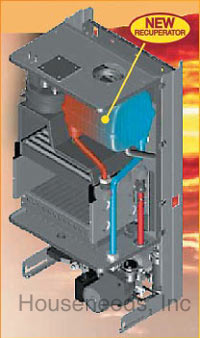
Biasi RivaPlus Condensing Gas Boilers
Heat Only or With Domestic Water - Propane and Natural High Efficency Gas Boilers
90% AFUE Condensing Gas Boiler
Output Modulates 41,600 BTU to 103,000 BTU
The RIVA Plus Boiler offers a unique condensing technology that increases the efficiency of the RIVA Compact and Combi Boilers to 90% AFUE. With the inclusion of a recuperator, the RIVA Plus can extract the remaining heat from the boiler's exhaust gas and transfer that heat into the return water destined for the boiler's primary heat exchanger. The recuperator guarantees higher efficiency and set-up simplicity. RIVA Plus is the only condensing wall-mounted boiler to offer this technology.
 The RIVA Plus Combi version is equipped with a flat plate heat exchanger which heats your domestic water whenever you open the hot water taps. The high efficiency design eliminates all the standby losses associated with storage tank water heaters.
Both RIVA Plus Combi and Compact Boilers maintain a constant high efficiency in both high and low temperature heating systems. Utilizing Biasi's Concept panel radiators, which heat at low water temperatures, will further increase efficiency by decreasing the average temperature of your heating system. For homeowners, Biasi RIVA boilers are not only quiet, dependable and efficient, they are more attractive and require less space than conventional boilers. And there is comfort in knowing that the sealed combustion heat exchanger provides the ultimate in safety while providing efficient central heating boiler and economical hot water supply with the Riba Plus Combi Model.
Combi Boilers: view all Combi Gas Boilers & Combi Propane Boilers
Combination Boilers: view all Combination Gas Boilers & Combination Propane Boilers
Condensing Boilers: view all Condensing Gas Boilers & Condensing Propane Boilers
Non Condensing Boilers: view all Non Condensing Gas Hot Water Boilers
Oil Fired Boilers: view all Oil Heating Boilers & Oil Boiler
Electric Boilers: view all Electrical Heating Boilers
Heat Only or With Domestic Water - Propane and Natural High Efficency Gas Boilers
Quiet and compact
The RIVA Plus Boiler offers a unique condensing technology that increases the efficiency of the RIVA Compact and Combi Boilers to 90% AFUE. With the inclusion of a recuperator, the RIVA Plus can extract the remaining heat from the boiler's exhaust gas and transfer that heat into the return water destined for the boiler's primary heat exchanger. The recuperator guarantees higher efficiency and set-up simplicity. RIVA Plus is the only condensing wall-mounted boiler to offer this technology.
The RIVA Plus Combi version is equipped with a flat plate heat exchanger which heats your domestic water whenever you open the hot water taps. The high efficiency design eliminates all the standby losses associated with storage tank water heaters. Both RIVA Plus Combi and Compact Boilers maintain a constant high efficiency in both high and low temperature heating systems. Utilizing Biasi's Concept panel radiators, which heat at low water temperatures, will further increase efficiency by decreasing the average temperature of your heating system. For homeowners, Biasi RIVA boilers are not only quiet, dependable and efficient, they are more attractive and require less space than conventional boilers. And there is comfort in knowing that the sealed combustion heat exchanger provides the ultimate in safety while providing efficient central heating boiler and economical hot water supply with the Riba Plus Combi Model.
Biasi RivaPlus Insides
Click on link below to search by Boiler Type:
Combi Boilers: view all Combi Gas Boilers & Combi Propane Boilers
Combination Boilers: view all Combination Gas Boilers & Combination Propane Boilers
Condensing Boilers: view all Condensing Gas Boilers & Condensing Propane Boilers
Non Condensing Boilers: view all Non Condensing Gas Hot Water Boilers
Oil Fired Boilers: view all Oil Heating Boilers & Oil Boiler
Electric Boilers: view all Electrical Heating Boilers
Thursday, April 1, 2010
It's Official! We're moving This June!
Click the link above to read our press release announcing our new showroom opening this June in Downtown Waitsfield, Vermont!
We plan on opening our new showroom on June 15th. In the meantime, a temporary showroom has been set up at our current office and warehouse location at 167 Mad River Canoe Road. All of our energy saving products such as Solar Hot Water Systems, Radiant Pex Heat Systems, Tankless Water Heaters, Wood and Wood Pellet Stoves, Whole House Fans, High Efficiency Boilers, and Solar Lights and Fans will be on display.
We plan on opening our new showroom on June 15th. In the meantime, a temporary showroom has been set up at our current office and warehouse location at 167 Mad River Canoe Road. All of our energy saving products such as Solar Hot Water Systems, Radiant Pex Heat Systems, Tankless Water Heaters, Wood and Wood Pellet Stoves, Whole House Fans, High Efficiency Boilers, and Solar Lights and Fans will be on display.
Friday, March 26, 2010
Solar Space Heating
Click the above link for a diagram.
In this configuration the storage tank employs a double heat exchanger, providing solar heat for the Radiant System, as well as solar Domestic Hot Water.
NOTE: This is only an example. Actual layouts vary from job to job.
The Solar Loop operates normally with a Differential Controller to heat the Twin Coil Tank through the bottom heat exchange coil.
The space heating pump runs when the Room Thermostat calls for heat.
This loop flows through the top coil in the tank. If the upper tank is below, say, 130ºF boiler controller redirects the flow through the boiler, activating the boiler at the same time. This preserves hot water in the tank for domestic use.
The bypass, incorporating a Mixing Valve and check valve, ensures that the floor system cannot overheat by mechanically recirculating it when a set temperature is reached.
Normally the set temperature of the immersion heater (just below the top coil in the tank) is set far enough below the boiler set temperature to ensure that the radiant system only takes the solar heat from the tank. In emergencies the immersion heater could be used to supplement the floor heat by raising the immersion heater set point.
How To Solder Copper Pipes
Click the above link for the diagram.
Caution: Please read and understand all safety information before attempting maintenance or repairs. Wear eye protection and gloves when soldering pipes and when working with flux. Flux is a toxic substance. Some equipment may rely on a cold water supply. Take appropriate steps to shut down any equipment that may be adversely affected by shutting off the water supply. Such equipment includes, but is not limited to, a boiler or other heating system.
Note: Because you are working with a flame, often in a confined space, be aware of flammable materials near where you are working. In some cases, you may need to set up a non-flammable heat shield between the solder joint and flammable material nearby. Check with your local authority for applicable codes about the work you wish to perform and the necessity of permits before you begin your project.
When copper pipes are fitted together, there is a very small gap between the two pieces. When the pipes are heated, and solder is touched to the pipes, the solder melts and is drawn up into the gap through capillary action. Once the gap is filled, and the heat removed, the solder forms a seal and makes a watertight joint. Soldering pipes is easy once you get the hang of it. The key is to recognize that you are heating the pipes, not the solder. The heated copper melts the solder. Follow the steps in this guide and you should be able to make watertight joints. It is recommended that you practice a few times on some spare parts until you feel confident.
Remove all burrs from the inside and outside edges of the pipe with a deburring tool. Small burrs can result in a variety of problems in the lifespan of the water supply system.
Clean the outside of the copper pipe to a brilliant shine with a copper pipe cleaning brush, or simply use steel wool or emery cloth. If the copper is not clean, the solder may not bond properly and the joint may leak.
Clean the inside of the female fitting in the same way as in step 1.
Apply acid-free flux to both the outside of the male fitting and the inside of the female fitting. Flux further cleans the copper plus helps to prevent oxidation as the pipe heats up. If the pipe becomes oxidized, the joint may leak.
Join the two pieces securely together.
Unroll about four inches of solder and straighten it. You will use the roll or container as a handle when applying the solder.
Light the torch and apply the flame to the joint. Move the flame around to ensure that you heat the pipe on the opposite side from you.
When the flux begins to bubble and spit, touch the tip of the solder to the joint. The solder should melt immediately and disappear into the joint. Remove the heat. Work quickly because the pipe's temperature will drop quickly. Move the tip of the solder around the entire joint to ensure that solder fills in all the way around. If the joint stopped taking up solder because the solder was not melting, then quickly add more heat so that more solder can be applied.
Once the joint will take no more solder it will build up outside of the joint and begin to drip. Care should be taken at this point. Disrupting a joint as it cools can result in a dry joint also known as a leak. Once the joint has hardened, it can be wiped. This is the part where experience/practice helps. Some people use a dry rag, so the joint can be cleaned, but not cooled to the point, where it creates a dry/leaky joint.
Notes:
Always check for leaks after the pipe has cooled.
If you overheat the copper, it will oxidize and that prevents the solder from bonding.
If the joint leaks, you must open the joint, remove all the solder and start over by cleaning the metal and applying flux. It may be easier to start over with new fittings.
Always use lead-free solder.
Make sure the pipes are completely dry or it will interfere with the bonding of the solder.
If you cannot completely stop the flow of water from the pipe you are working on, it may be impossible to heat the pipe hot enough. Take a wad of white bread (without the crust) and stuff it into the pipe. This will hold the water back for a minute or two. After that the bread will dissolve harmlessly in the pipe and is easily flushed out.
Specialty parts may have requirements to disassemble seals or other components. Please read all instructions from each manufacturer.
When sweating ball valves, it is best to point the flame away from the piece, sweating the ball valve as quick as possible.
If you use MAPP gas instead of propane, it burns much hotter and will heat the copper very quickly compared to propane. If you are used to propane, practice with MAPP before beginning work.
We do not Recommend open-loop heating systems
Why?
The low temperatures of a radiant floor system can become a breeding ground for potentially fatal bacteria. This opinion is based upon our experience along with national, state and university studies and warnings.
Contracting potentially fatal, pneumonia-like Legionnaires' disease from hot water that isn't hot enough (Legionella is a water-borne bacterium and is the cause of Legionnaires disease).
Indeed, the federal Centers for Disease Control website ( www.cdc.gov) says that 8,000 to 18,000 people contract Legionnaires' disease each year, with the illness fatal in 5%-30% of the cases. The study recaps data documenting the presence of Legionella bacteria in residential water systems because of water heaters being set above 95°F and below 140°F is a perfect habitat for growth. Because the bacterium enjoys warm water environments, it's a potential problem in hot water distribution systems.
When your domestic hot water tank exceeds temperatures above 120°F, it is important to put in an anti scalding mixing valve to prevent scalding injuries.
We would be happy to help you with a closed system using a heat exchanger or primary/secondary loops.
Traditional Tank Water Heater as a Heat Source
Click link above for diagram.
The example below shows a setup using a tank-type hot water heater as a closed loop heat source. It is recommended that this type of system be used for small heat loads only.
This is only an example. Actual layouts vary from job to job.
The example below shows a setup using a tank-type hot water heater as a closed loop heat source. It is recommended that this type of system be used for small heat loads only.
This is only an example. Actual layouts vary from job to job.
Traditional Tank Water Heater as a Heat Source
Click link above to view diagram.
The example below shows a setup using a tank-type hot water heater as a closed loop heat source. A mixing valve is added for adjusting the temperature for a concrete or wood floor. It is recommended that this type of system be used for small heat loads only.
This is only an example. Actual layouts vary from job to job.
How to Fill and Purge your Hydronic Heating System
Click on the link above to view the diagram.
A properly plumbed hydronic heating system makes it easy to add water and remove air, during the initial fill / purge and in later servicing.
We remove all of the air to make the hydronic heating system work mechanically correct. Small amounts of air can cause gurgling noises and large amounts of air can cavitate the circulators pumps causing the heating loop to stop flowing, resulting in a lack of heat.
When filling or purging a hydronic heating system, it is easiest when the system is broken down into smaller sections or loops. Each loop / zone is connected to the hydronic boiler fill valve and has the ability to be isolated from the other loops. Ball valves and drains isolate the system.
Water is introduced into the hydronic system in one way, flowing down the piping and out the boiler drain, carrying the air with it.
The process of isolating and filling is repeated until the hydronic system is full of water and the air removed.
Flushing the hydronic system works in reverse, replacing the old water with new. Flushing the hydronic system is important. The hydronic heating system should be flushed to remove and flux or solder that may be mixed in the water.
Boiler Primary Loops and Boiler Secondary Loops
Click on the link above for examples of Primary Loop Piping:
Primary/Secondary Loop Piping is commonly used in heating systems with multiple temperature zones.
This also works well with condensing boilers allowing proper flow through the boiler for the highest rate of heat delivery.
Primary/Secondary Loop Piping is commonly used in heating systems with multiple temperature zones.
This also works well with condensing boilers allowing proper flow through the boiler for the highest rate of heat delivery.
Hot Water Boiler with Primary Secondary Hydronic Heating with 5 Zones (High and Low Temperature) and Indirect Domestic Hot Water Tank
Click on the link above for the diagram.
This is an example of how to use a Gas Boiler to produce different water temperatures for 5 zones (High / Low Temperatures) plus a zone for the Indirect Hot Water Tank.
You will notice that in this example there are 3 possible temperatures for the heating zones. There are 3 zones for high temperature that can feed radiators or baseboard convectors at whatever the boiler water temperatures is set to. There are 2 zones for a set temperature that could be used for pex radiant heat zones at different water temperatures.
This is only an example. Actual layouts vary from job to job.
Hot Water Boiler with Primary / Secondary Hydronic Heating Loops with 3 Temperature Heating Zone
Click on the link above for the diagram.
This is an example of how to get different temperatures from a set temperature heat source. This is an example of how to use a Gas Boiler to produce different water temperatures for 4 zones (High / Low Temperatures)..
You will notice that in this example there are 3 possible water temperatures for the heating zones. There is 1 zone for high temperature that can feed radiators or baseboard convectors at whatever the boiler temperatures is set to. There are 2 zones for a set temperature that could be used for pex radiant heat zones at 2 different water temperatures.
This is only an example. Actual layouts vary from job to job.
Subscribe to:
Posts (Atom)